地图构建
二维码地图
建图主要分为四大步骤
- 配置建图参数
- 执行建图
- 保存地图至本地
- 将地图上传至数据库
A. 配置建图参数
- 准备一台用于建图的电脑(已安装Bito建图软件)、一个相机(带特殊镜头且内参已标定)和一根相机连接电脑的线
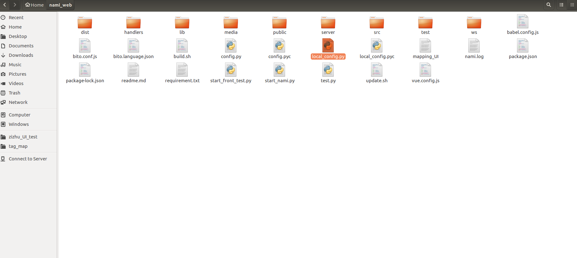
- 在home/nami_web/文件夹下打开名为local_config.py的文件
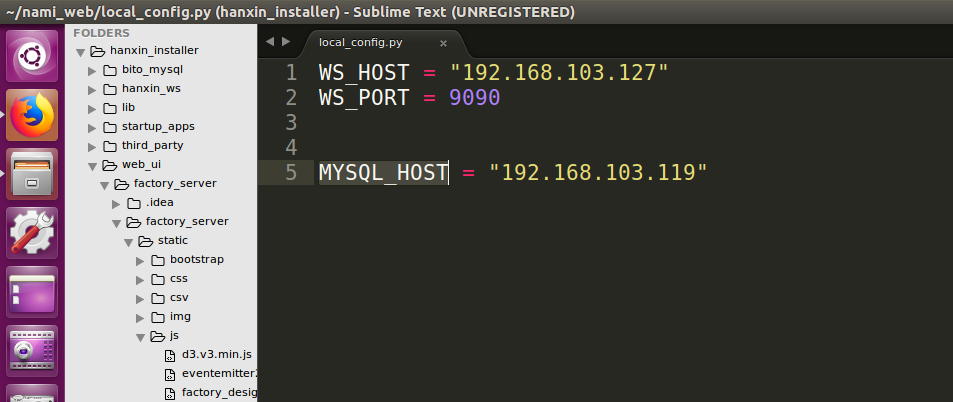
- 在上一步打开的文件中设置WS_HOST为本机IP地址,设置MYSQL_HOST为当前韩信的IP地址,并保存
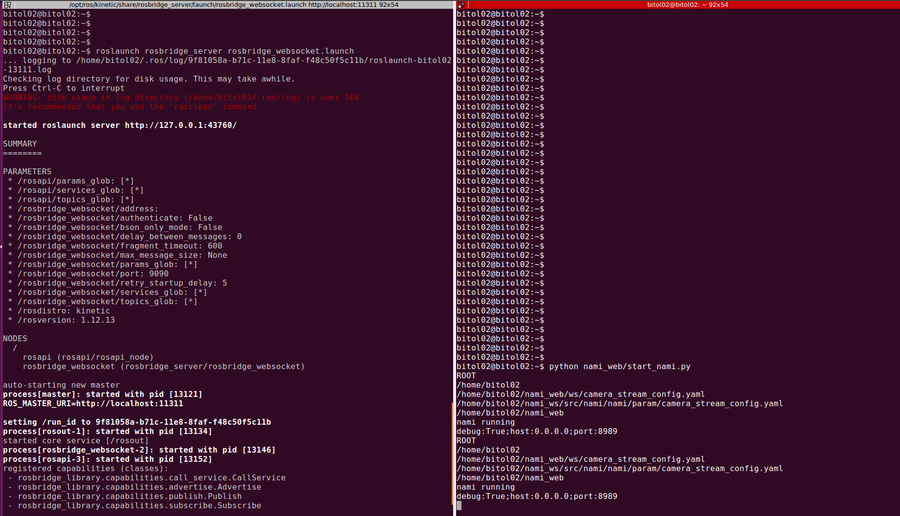
4. 在terminator里打开 2个终端,分别输入命令: (1)roslaunch rosbridge_server rosbridge_websocket.launch (2)python nami_web/start_nami.py
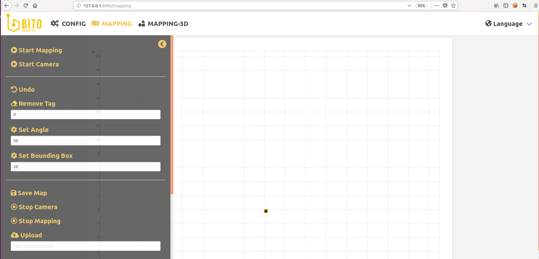
- 打开浏览器,在地址栏中输入:127.0.0.1:8989
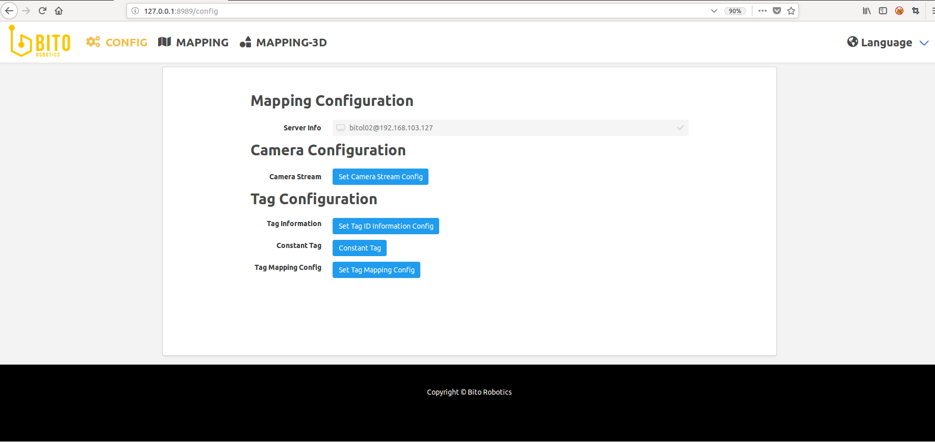
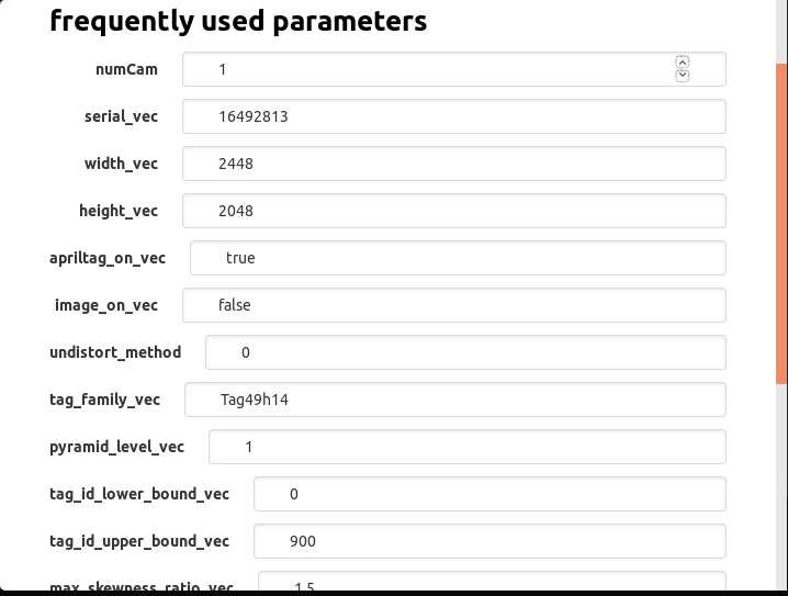
- 点击”Set Camera Strem Config”,根据部署现场实际的情况,在弹窗中修改“tag_family_vec” (二维码类型,默认为Tag49h14)、“tag_id_lower_bound_vec” (部署现场用到的最小二维码号码)和”tag_id_upper_bound_vec” (部署现场用到的最大二维码号码),确认修改后点击“Submit Camera Config”
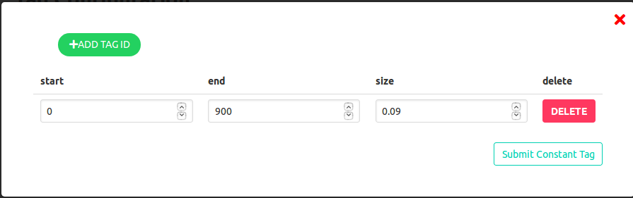
- 点击”Set Tag Information Config”,根据部署现场实际的情况,在弹窗中填写二维码号码及对应的尺寸信息,确认后点击“Submit Tag ID Info Config”
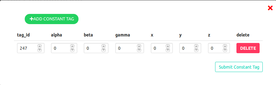
- 点击”Set Constant Tag”,根据部署现场实际的情况,在弹窗中填写建图初始二维码号码,其他设置为0,确认后点击“Submit Constant Tag”
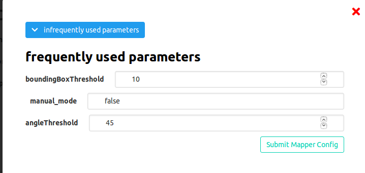
- 点击”Set Tag Mapping Config”,根据现场实际情况,在弹窗中修改”boundingBoxThreshold” (默认值为10)和”angleThreshold” (默认值为45),确认后点击“Submit”;
B. 执行建图
- 连接电脑和相机,相机安装高度约为2m, 角度垂直向下,携带建图设备行走至建图初始二维码号码处
- 切换到Mapping页面, 点击”Start Mapping”和”Start Camera”开始建图
- 按照预定行走路线扫描地图中的二维码,建议行走路线为增量式行走,建图时应尽量保证相机能同时看到已加入地图中的二维码和未加入地图中的二维码
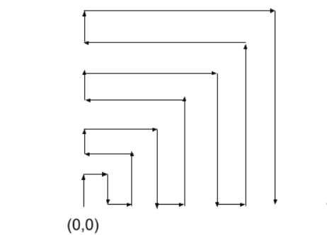
- 当新加入的二维码在地图中的位置与实际二维码在地图中的位置差距过大时,点击“Undo”撤销上一步加入的二维码
- 当需要删除某个二维码时,输入二维码号码并点击”Remove Tag”, 会删除此二维码及在此二维码之后新加入地图中的二维码
- 当发现二维码比较难以加入地图中时,可适当增大角度参数(0~90)并点击”Set Angle”,也可以适当增大绑定框(0~50)并点击”Set Bounding Box”
C. 保存地图至本地
- 当得到想要的地图时,点击”Save Map”保存地图至本机
- 点击“Stop Camera”和”Stop Mapping”关闭相机,结束建图
D. 将地图上传至数据库
- 当需要为地图命名时,输入英文名字并点击“upload”, 将地图上传至数据库;当不需要为地图命名时,直接点击”upload”, 系统将会自动给地图分配一个名字
温馨提示
- 建图过程中当地图效果比较好时,记得常点击”Save Map”保存地图
- 新加入的二维码初始位置不太好时,在此二维码周围多停留,让相机以不同角度看到二维码,待其调整为较好位置时,再继续建图
点云地图(中文版)
在线建图主要分为四大步骤
- 配置激光建图软件参数并打开软件
- 检查激光雷达等驱动设备是否正常工作
- 设置rviz
- 建立地图并保存
离线建图主要分为五大步骤
- 录制bag(在线建图时可同步进行bag录制)
- 配置激光建图软件参数并打开软件
- 打开录制好的包并检查相关topic是否正常发布数据
- 设置rviz
- 建立地图并保存
定位手动开启主要分为三大步骤(默认开机自启)
- 配置激光定位软件参数并打开软件
- 检查激光雷达等驱动设备是否正常工作
- 查看定位效果
A. 配置激光建图软件参数并打开软件
- 准备一台用于建图的电脑(已安装Bito建图软件),以下步骤使用Velodyne激光及Imu传感设备进行建图为例。
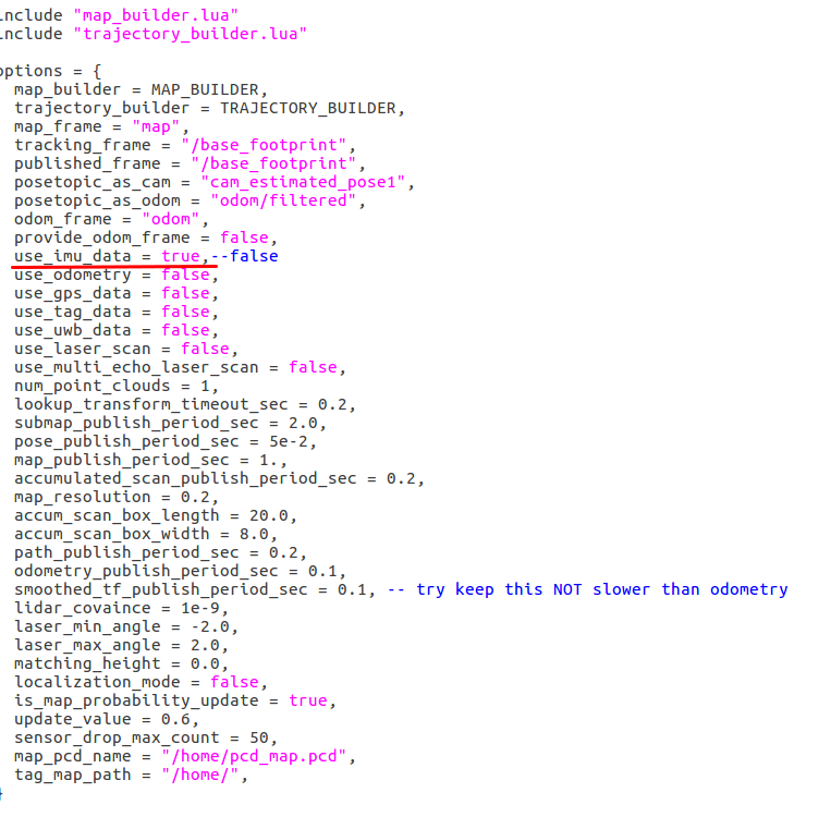
- 打开激光建图参数配置文件,将use_imu_data设为true,lua文件参数修改后不需要重新编译。(有源码的参数配置文件目录为:~/yugong_ws/src/cartographer_ros/cartographer_ros/configuration_files/mapping_with_velodyne.lua 无源码的参数配置文件目录为:~/yugong_ws/install/share/cartographer_ros/configuration_files/mapping_with_velodyne.lua)
(注意: 不同的传感设备及参数的配置请详见 lua参数文件详解)。
- 打开一个终端,输入以下命令。(ygxxxxxxx代表主机名)
$ rosnode kill /ygxxxxxxx/cartographer_node
$ source ~/yugong_ws/devel/setup.bash --extend
$ roslaunch cartographer_ros mapping_by_velodyne.launch
B.检查激光雷达等驱动设备是否正常工作
- 输入以下命令查看topic列表,不同的设备topic的名字不一致:
$ rostopic list
- 在命令行中输入下面命令查看激光雷达等设备是否运行(注意:请事先确认使用了哪些设备,并逐一检查各个设备是否正常工作,例如本例子还使用了Imu):
$ rostopic echo /ygxxxxxxx/velodyne_points
$ ^C (Ctrl+c)
$ rostopic echo /imu(Imu的topic name无主机名前缀)
- 如果激光雷达等设备未正常工作请输入以下命令打开(其他设备的开启请自行确认相应的驱动包,如Imu等):
$ roslaunch velodyne_pointcloud VLP16_points.launch (Velodyne的驱动开启命令)
$ roslaunch xsens_driver xsens_driver.launch (Imu的驱动开启命令)
(注意,Imu等USB接口的传感器,第一次安装使用时请先使用以下命令给USB接口权限)
$ sudo chmod 777 /dev/ttyUSB*
C. 设置rviz
1. 一般情况下,当运行步骤A的时候会就会弹出rviz的界面,但是当rviz文件没有跳出来的时候,运行下面命令。
$ rosrun rviz rviz
- 点击rviz的界面”ADD”添加所需的对象,比如观测路径则添加对应的path。

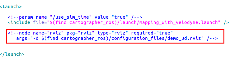
(注意,若所使用的机器人无显示器,则需要在mapping_by_velodyne.launch文件中关闭rviz,不然可能导致软件无法运行,launch文件目录为:~/yugong_ws/src/cartographer_ros/cartographer_ros/launch/mapping_by_velodyne.launch,操作与下图红色框内一样,将rviz注释掉)
D. 建立地图并保存
- 将机器人围着所需建图的场地走动(尽量让机器人在整个场地各个地方走一遍,起始点与终止点需要是同一个,建图过程中请录制相关的bag以供离线建图时使用,bag录制及离线建图步骤请详见下文)。
- 打开一个新的命令框,运行以下命令。
$ source ~/yugong_ws/devel/setup.bash --extend
$ rosservice call "/ygxxxxxxx/finish_trajectory" "map"
$ cd ~/.ros
$ cp map.pcd ~/catkin_slam/pcd_map/map.pcd
(注意:若无catkin_slam目录,请在根目录下自行创建catkin_slam文件夹或是将~/.ros路径下的map.pcd文件存放在自定义位置,但是存放路径及pcd文件名请与localization_with_velodyne.lua的参数配置文件里保持一致。不然可能会导致使用定位软件的时候无法顺利找到所建地图并成功定位。有源码的参数配置文件目录为:~/yugong_ws/src/cartographer_ros/cartographer_ros/configuration_files/localization_with_velodyne.lua 无源码的参数配置文件目录为:~/yugong_ws/install/share/cartographer_ros/configuration_files/localization_with_velodyne.lua)

- 建图完成并存图后请及时关闭建图软件。
E. 录制bag(在线建图时可同步进行bag录制)
- 请使用以下命令查看所有的topic name
$ rostopic list
- 使用以下命令录制bag(建议录制所有所需的传感器的topic,本文以录制velodyne,imu及odom里程计为例)
$ rosbag record /ygxxxxxxx/velodyne_points /imu /ygxxxxxxx/odom/wheel
- 将机器人围着所需建图的场地走动(尽量让机器人在整个场地各个地方走一遍,起始点与终止点需要是同一个),录制完成后请及时使用以下命令关闭
$ ^C (Ctrl+c)
F. 配置激光建图软件参数并打开软件
- 打开mapping_with_velodyne.lua文件进行参数配置,录制并使用了哪些传感器设备请在lua文件里进行相应的参数配置,本步骤与在线建图的参数配置步骤一致,请详见上文。
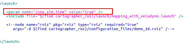
- 打开mapping_by_velodyne.launch文件,按照下图红色框中的操作取消use_sim_time的注释(文件目录为:~/yugong_ws/src/cartographer_ros/cartographer_ros/launch/mapping_by_velodyne.launch)。
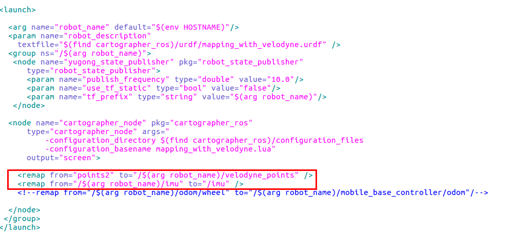
- 打开mapping_with_velodyne.launch文件,按照下图红色框中的操作将topic名字重命名(录制bag时的主机前缀与建图时的机器人主机名不一致,所以请手动remap激光建图软件的topic名称,与bag的topic名字保持一致,若不确定所录bag的topic名称,请参考下文步骤G的1与2进行查看,文件目录为:~/yugong_ws/src/cartographer_ros/cartographer_ros/launch/mapping_with_velodyne.launch)
- 打开一个终端,输入以下命令打开激光建图软件。(ygxxxxxxx代表主机名)
$ rosnode kill /ygxxxxxxx/cartographer_node
$ source ~/yugong_ws/devel/setup.bash --extend
$ roslaunch cartographer_ros mapping_by_velodyne.launch
G. 打开录制好的包并检查相关topic是否正常发布数据
- 使用以下命令打开录制的包
$ rosbag play bag_name.bag --clock
- 打开topic列表
$ rostopic list
- 使用以下命令检查相关topic是否正常发布数据(本文以velodyne、Imu及odom里程计为例子)
$ rostopic echo /ygxxxxxxx/velodyne_points /imu /ygxxxxxxx/odom/wheel
$ ^C (Ctrl+c)
$ rostopic echo /imu
$ ^C (Ctrl+c)
$ rostopic echo /ygxxxxxxx/odom/wheel
$ ^C (Ctrl+c)
H. 设置rviz
本步骤与在线激光建图的步骤C.设置rviz一致,请参考上文。
I. 建立地图并保存
本步骤与在线激光建图的步骤D.建立地图并保存一致,请参考上文。
J. 配置激光定位软件参数并手动打开软件
- 建图步骤完毕后,请重启电脑使定位软件自动开启在该电脑上或运行以下命令手动打开定位软件
$ source ~/yugong_ws/devel/setup.bash --extend
$ roslaunch cartographer_ros localization_by_velodyne.launch
K. 检查激光雷达等驱动设备是否正常工作
- 该步骤与建图时检查激光雷达等驱动设备是否正常工作的步骤一致,请参考上文
Points_Cloud map(English)
Online mapping with 4 steps
- Configure parameters and run mapping function of Bitographer
- Check the sensing device if works or not, such as Lidar
- Setting for RVIZ
- Build the map and save
Offline mapping with 5 steps
- Record the bag(Suggest: record the bag while online mapping)
- Configure parameters and run mapping function of Bitographer
- Play the bag and check if the data was published successful from topic or not
- Setting for RVIZ
- Build the map and save
Localization by manual mode with 3 steps(Default boot)
- Configure parameters and run localization function of Bitographer
- Check the sensing device if works or not, such as Lidar
- Check the accuracy of localization
A. Configure parameters and run mapping function of Bitographer
- A computer with Bitographer
This situation will use Velodyne lidar and Imu to do mapping and localization
- Configure parameters in mapping_with_velodyne.lua
- Set ‘use_imu_data=true’
- File is located in the source code at src:~/yugong_ws/src/cartographer_ros/cartographer_ros/configuration_files/mapping_with_velodyne.lua
- Without the source code, the file is located at src:~/yugong_ws/install/share/cartographer_ros/configuration_files/localization_with_velodyne.lua
- Note, Bitographer need not be compiled after changing the parameters in lua files.
(Comment: Please check the pdf file to find more details about configuring parameters for different sensing devices configuring parameters for lua files. Note that if wheel odometry sensor input is not being used, set TRAJECTORY_BUILDER_3D.kalman_local_trajectory_builder.pose_tracker.use_odom_angle to false)
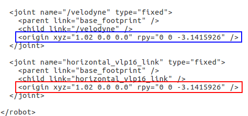
- Configure the urdf in mapping_with_velodyne.urdf to reflect the location of your sensors. The file can be found in src:~/yugong_ws/src/cartographer_ros/cartographer_ros/configuration_files/mapping_with_velodyne.urdf. For example, if the velodyne is centrally located 1 meter above the mobile base and has its local x and y axes aligned with the robot’s x and y axes, change the origin of the velodyne joint to be <origin xyz=”0.0 0.0 1.0” rpy=”0 0 0” /> as shown below. Note that the box outlined in red defines the transform between base_footprint and horizontal_vlp16_link wherease the box outlined in blue defines the transform between base_footprint and /velodyne. Modify whichever one that corresponds to the frame the velodyne driver is publishing to. This can be determined by checking the launch file in the velodyne_pointcloud package. For example, in VLP16_points.launch, the data is published to the horizontal_vlp16_link frame and in 32e_points.launch, the data is published to the /velodyne frame.
Note, Bitographer does not need to be recompiled after modifying the urdf.
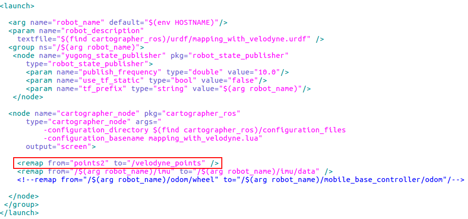
- If using the research platform (which uses a HDL32e LiDAR running the 32e_points.launch file), open mapping_with_velodyne.launch, follow the picture with red frame to remap the velodyne topic name. File path:~/yugong_ws/src/cartographer_ros/cartographer_ros/launch/mapping_with_velodyne.launch). Note, Bitographer does not need to be recompiled after modifying the launch file.
- Open another terminal and type the commands(ygxxxxxxx is hostname)
$ rosnode kill /ygxxxxxxx/cartographer_node
$ source ~/yugong_ws/devel/setup.bash --extend
$ roslaunch cartographer_ros mapping_by_velodyne.launch
B. Check the sensing device if works or not, such as Lidar
- Type the command to check the topic list,differrent devices with different topic name
$ rostopic list
- Use the commands to check the the sensing device if works or not (Comment: Please make sure of the topic name(hostname may not be in front) and what kind of sensing devices will be used first,and check each sensing device is working or not,such as imu)
$ rostopic echo /ygxxxxxxx/velodyne_points
$ ^C (Ctrl+c)
$ rostopic echo /ygxxxxxxx/imu
- If sensing device are not working, please use these commands (Different devices with different driver package). Note, if using HDL32e LiDAR, replace VLP16_points.launch with 32e_points.launch.
$ roslaunch velodyne_pointcloud VLP16_points.launch (Velodyne' driver package)
$ roslaunch xsens_driver xsens_driver.launch (Imu' driver package)
(Comment: Some sensing devices with USB interface such as imu need to use command to give the permission for USB interface)
$ sudo chmod 777 /dev/ttyUSB*
C. Setting for RVIZ
- RVIZ will be opened automatic when do step A, but if RVIZ was not opened automatic, please use the command
$ rosrun rviz rviz
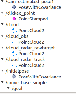
- Click “Add” and then “By topic” to add topics in RVIZ. Good topics for visualization include:
- /map_cloud to see the 3D map being built as a pointcloud
- /scan_matched_points2 to see where the current scan matches the points in the map
- /velodyne_points to see the velodyne pointcloud output
- /cam_estimated_pose1 to see where the robot the robot pose is within the map
To visualize the robot model, add it through the “Display Type” tab. Then modify the RobotModel’s Robot Description and TF Prefix arguments in RVIZ with /<hostname>/yugong_description and /<hostname> respectively.
(Comment: If the robot used does not have a dispaly, please comment out the rviz node in mapping_by_velodyne.launch. Otherwise, it will cause Bitographer to not work. Follow the picture with red frame. File path:~/yugong_ws/src/cartographer_ros/cartographer_ros/launch/mapping_by_velodyne.launch)
D. Build the map and save
- Move the robot around the factory (Try to navigate the robot through the entire site - the starting point and the ending point need to be the same. Record bags for offline mapping while mapping online, more details about recording bag and offline mapping please find in next steps)
- Open another terminal and type the commands
$ source ~/yugong_ws/devel/setup.bash --extend
$ rosservice call "/ygxxxxxxx/finish_trajectory" "map"
$ cd ~/.ros
$ cp map.pcd ~/catkin_slam/pcd_map/map.pcd
(Comments: If there is no catkin_slam directory, please create the catkin_slam folder with a pcd_map subfolder in the root directory or store the map.pcd file in the ~/.ros directory in a custom location. Just make sure the file path matches the file path set to the map_pcd_name parameter located within the localization_with_velodyne.lua file. Otherwise, the map cannot be successfully located when using the localization software. The configuration file path of the source code is: src:~/yugong_ws/src/cartographer_ros/cartographer_ros/configuration_files/localization_with_velodyne.lua. The file path without source code is src:~/yugong_ws/install/share/cartographer_ros/configuration_files/localization_with_velodyne.lua)
- Close the Bitographer when complete and save the map.
E. Record the bag(Comment: can record bag while online mapping)
- Type the command to check the topic list
$ rostopic list
- Use the command to record the bag. (Suggest: record all sensing devices’ topic (hostname may not be in front), in this situation will record velodyne, imu and odom topics)
$ rosbag record /ygxxxxxxx/velodyne_points /ygxxxxxxx/imu /ygxxxxxxx/odom/wheel
- Move the robot around the factory (Try to navigate the robot through the entire site - the starting point and the ending point need to be the same. Use the command to stop recording.
$ ^C (Ctrl+c)
F. Configure parameters and run mapping function of Bitographer
- Open mapping_with_velodyne.lua to configure parameters, make sure what kinds of sensing device’topic are recorded and changing the parameters like online mapping.
- Open mapping_by_velodyne.launch,follow the picture with red frame to cancel the comment for ‘use_sim_time’.(File path:~/yugong_ws/src/cartographer_ros/cartographer_ros/launch/mapping_by_velodyne.launch)
- Open mapping_with_velodyne.launch, follow the picture with red frame to remap the topic name (Different computer to record the bag with different hostname, please remap Bitographer’ topic name to make sure the topic name are the same with bag’s topic name,if you are not sure the bag’s topic name, please follow step G 1 and 2. If the bag file is being run on a different computer, then launch a static transform publisher between the frames associated with the different computer’s hostname (such as for velodyne and IMU) to the frame of the robot as shown below. File path:~/yugong_ws/src/cartographer_ros/cartographer_ros/launch/mapping_with_velodyne.launch)
Static TF example for velodyne:
<node pkg="tf" type="static_transform_publisher" name="bito_to_robot" args="0 0 0 0 0 0 bitol15/horizontal_vlp16_link yg00a00019040513000g00/horizontal_vlp16_link 100" />or
rosrun tf static_transform_publisher 0 0 0 0 0 0 bitol15/horizontal_vlp16_link yg00a00019040513000g00/horizontal_vlp16_link 100
- Open a terminal and type the command to run the software(ygxxxxxxx is hostname)
$ rosnode kill /ygxxxxxxx/cartographer_node
$ source ~/yugong_ws/devel/setup.bash --extend
$ roslaunch cartographer_ros mapping_by_velodyne.launch
G. Play the bag and check if the data was published successful from topic or not
- Use the command to play the bag
$ rosbag play bag_name.bag --clock
- Check topic list
$ rostopic list
- Type the command in terminal to check if the data was published successful from topic or not (In this situation will check velodyne, Imu and odom’topic. Note, hostname may not be in front)
$ rostopic echo /ygxxxxxxx/velodyne_points /ygxxxxxxx/imu /ygxxxxxxx/odom/wheel
$ ^C (Ctrl+c)
$ rostopic echo /ygxxxxxxx/imu
$ ^C (Ctrl+c)
$ rostopic echo /ygxxxxxxx/odom/wheel
$ ^C (Ctrl+c)
H. Setting for RVIZ
This step is the same with online mapping’ step C
I. Build the map and save
This step is the same with online mapping’ step D
J. Configure parameters and run localization function of Bitographer
- Configure localization_with_velodyne.lua as was done in section A step 2 by mapping.
- Configure localization_with_velodyne.urdf as was done in section A step 3 by mapping.
- Configure localization_with_velodyne.launch as was done in section A step 4 by mapping.
- Run the software of manual mode by using the commands.
$ source ~/yugong_ws/devel/setup.bash --extend
$ roslaunch cartographer_ros localization_by_velodyne.launch
K. Check the sensing device if works or not, such as Lidar
- This step is the same with online mapping’ step B
L. Check the accuracy of localization
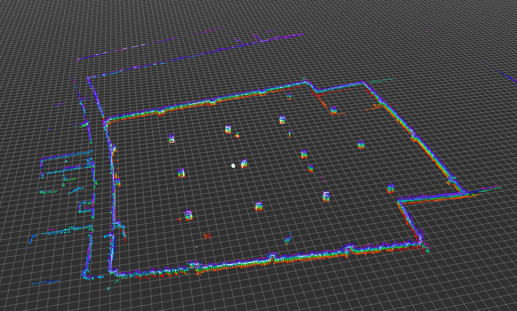
- Open RVIZ to check the map_cloud and points_cloud is matching or not(Colorful points are the map_cloud, white points are points_cloud, setting RVIZ is the same with online map)
- If localization is taking a long time to occur (or is not occuring), try bringing the robot close to the map origin and/or modify the parameter below in localization_with_velodyne.lua to be 0.0. Then relaunch localization.
TRAJECTORY_BUILDER_3D.kalman_local_trajectory_builder.initial_pose_z = 0.0